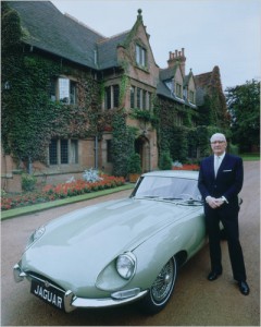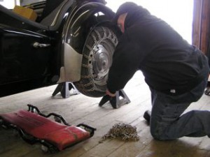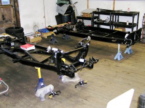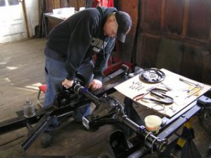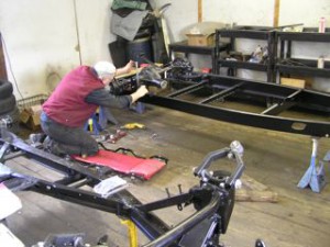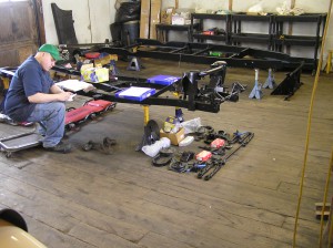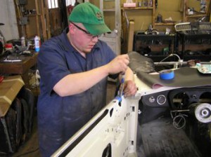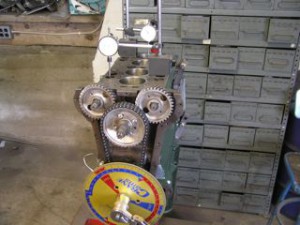
First Lea-Francis cam timing set up .

Jaguar cam timing chart
Here’s a picture from a few weeks back, of the cam timing process for the Lea-Francis engine pictured here, but there’s a mistake. Here’s a clue: This is a hemi engine. Still puzzled? Let’s do some cam timing 101
The chart at the right is taken from the Haynes Owner’s Workshop Manual for the Mk 2. E-type cam timing is the same, by the way. What the chart illustrates is what we refer to as a “Split Overlap”, meaning the opening & closing events are evenly distributed around top & bottom dead center. We’ll get to the practical aspects of that in a few moments. But first, some critical terms: TDC is Top Dead Center, where the piston is at the top of its stroke. BDC, reasonably enough, is therefore Bottom Dead Center, where the piston is (drum roll, please !) at the bottom of its stroke. B’s & A’s are Before & After.

Standard Lea-Francis cam timing
This chart is the standard cam timing for Lea-Francis. What it’s telling us is that the intake & exhaust cams are not ground symmetrically. If you take the 10 BTDC intake opening, add the 180 degrees between top & bottom dead center, and then add the 45 ABDC closing, you have a DURATION of 235 degrees valve open time, but if you do the same math on the exhaust side, your duration is 250 degrees.

Timing chart for Lea-Francis Sports
This is the cam timing chart for a Lea-Francis Sports (page back to “Coventry Twin Cams” if you’re wondering what that is). O.K let’s do the numbers again with this one: Yes, you’re absolutely correct, BOTH cams have a 272 degree duration, but if you’ve been paying close attention, you also know that we’re not looking at a split overlap. So what’s going on here ? Well, let’s do a little more math. Try ADDING 2.5 degrees to these timing events. What happens when you do this is pretty interesting. All of a sudden the intake opens at 20.5 BTDC & closes 71.5 ABDC, and the exhaust opens at 71.5 BBDC & closes 20.5 ATDC, which, of course, is our SPLIT OVERLAP. These cams are installed 2.5 degrees advanced, which is a useful way to move the torque band lower down the RPM range.
In order to gain some perspective about these two cam timing charts, let’s make some comparisons to another 1800 cc engine, the MGB. The duration of the standard 88G 303 cam in a ’60’s MGB is 252 degrees, pretty much the same as the exhaust side of a standard Lea-Francis. Our favorite bump up cams for this engine, the Piper BP 270 & the APT VP 11BK run a 272 degree duration, which again, is valve open time.
By now you might be wondering why the intake & exhaust valves are both partially open at least some of the time. It’s what Ed Iskenderian called the “5th cycle”. Because the intake valve starts to open before the exhaust valve is fully closed, the exiting exhaust gases create a vacuum which pulls the entering air/fuel mixture into the cylinder more efficiently, up to a point. That point usually being at lower RPM when the gas velocities are relatively low and you’ll hear the characteristic choppy idle that tells you the car’s been cammed up.

First Lea-Francis cam timing trial
Well now, here’s the chart of our first Lea-Francis cam timing trial. We’re timing at what Iskenderian calls .050″ lifter rise. It looks like it’s pretty close to a split overlap, but the numbers are all wrong. This timing is almost upside down. The intake valve is opening so far after TDC that the engine probably wouldn’t even run. So what’s the problem ? Well, Duh-Hey, it’s a HEMI.
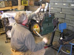
David checks cam timing at cam follower angle
In an engine with hemispherical combustion chambers, the valves are inclined at an angle from the vertical. There are several advantages to this arrangement, one of which is the “straight thru” path for combustion gases, and another is more room for bigger valves, just like the Jaguar six cylinder engine, except it was actually the other way around. My mistake, boldly illustrated in the first picture, was to check the cam timing vertically instead of on the opening & closing angle. Once I finally realized why the numbers didn’t work, I wired the followers into the head (the only way to get them in the block), dropped the head on, and checked it again.

Final cam timing chart with about three degrees of advance
So here we are again, a more or less split overlap with about 2.5 degrees of advance, but a much smaller duration. Why ? Well, we’re checking by the Isky method at .050″ lifter rise, meaning once the cam follower has travelled .050″ up the cam lobe. And why are we doing that ? For vastly better accuracy. This, perforce, makes the duration shorter than when you measure at the valve. Let me explain:
As you can see from the pictures, we’re using two measuring devices, the degree wheel and the dial indicator. The degree wheel gives us piston location measured in degrees between top & bottom dead center, and the dial indicator measures the travel of the cam follower, or lifter (lifta’, if you’re from New England).
At the moment that the dial indicator begins to indicate the movement of the cam follower, the degree wheel is moving much faster, but when you get to .050″ of “lift” an interesting phenomena occurs, the velocities are reversed. What this means in practical terms is that the potential checking error is much reduced. A checking error of say .005″ on the dial indicator is probably only an error of 1 degree on the degree wheel. Trying to calculate that initial opening or final closing event, your checking error is going to go against you big time.
And that brings us back, for a moment to that MGB engine. If you’re ever parsed the Factory Repair Manual, you may have noticed a fairly esoteric specification called “Checking Clearance at TDC” or something like that, which from memory is about .055″. The British Motor Corporation knew that because of such things as manufacturing tolerances, theoretical vs. actual rocker arm ratios (1.4:1, same as a LEAF), or even wear on a feeler gauge, it was a hopeless crapshoot to try to calculate an actual opening event. So they provided a more reliable one, which is the feeler gauge equivelent of the Isky method. If that factory cam is installed correctly, the valve should just start to open at TDC if you’ve clearanced the #1 intake rocker arm to .055″.
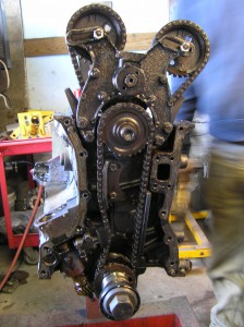
Stretch in lower timing chain a4.2 E-type engine. Click here for enlargement
Patrick stripped this 4.2 E-type engine earlier this week, but before he did, he recorded the cam timing, just in case it was anything unusual. It was. In fact it was about 5 degrees retarded. we think we know the reason. Take a look at the stretch in the lower timing chain at the chain tensioner. This car went like a ball of fire above about 4000 rpm.
A special thanks to David Pound, who converted the cam timing charts to J-Pegs after your scribe couldn’t figure out why he couldn’t import them to this page as PDF’s.

